

ATV212H075N4 – Schneider Electric
TellitavTimeout setting from 0.1 to 100 s
Write Single Register (06)
Write Multiple Registers (16) 2 words maximum
Inhibitory Watch
Read Holding Registers (03) 2 words maximum
METASYS N2
APOGEE FLN
LonWorks
BACnet
Internal supply: 24 V DC (21… 27 V), <200 A, protection type: overload and short circuit protection
5 A at 30 V DC on resistive load - cos phi = 1 - L/R = 0 ms (FL, R)
2 A at 250 V AC on inductive load - cos phi = 0.4 - L/R = 7 ms (FL, R)
2 A at 30 V DC on inductive load - cos phi = 0.4 - L/R = 7 sc (FL, R)
FLA, FLC 7 ms, tolerance +/- 0.5 ms for digital output(s)
FLB, FLC 7 ms, tolerance +/- 0, 5 ms for digital output(s)
RY, RC 7 ms, tolerance +/- 0.5 ms for digital output(s)
0.6 Nm (VIA, VIB, FM, FLA, FLB, FLC, RY, RC, F, R, RES )
12...16 kHz with reduction factor
Automatic whatever the load
Adjustable
1 RJ45
1.7A at 380V
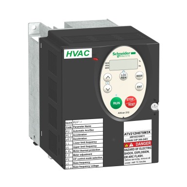
0.55…1 kW at 480…500 V 3 phases
2.2A at 460V
Negative logic (sink) (F, R, RES), >= 16 V (state 0 ), <= 10 V (state 1)
L1/R, L2/S, L3/T: bornier 6 mm² / AWG 10
2 ms +/- 0.5 ms R digital
2 ms +/- 0.5 ms RES digital
3.5 ms +/- 0.5 ms VIA analog
22 ms +/- - 0.5ms analog VIB
VIB: +/- 0.15% of maximum value for input
FM: +/-0.2% for output
5092 V DC between control and power supply terminals
Thermal power stage: drive
Short-circuit between motor phases: drive
Input phase breaks: drive
Overcurrent between output phases and ground: drive
Overvoltage on the DC bus: drive
Break on the control circuit: drive
Against speed limit exceeded: drive
Power supply overvoltage or undervoltage: drive
Power supply undervoltage: drive
Against input phase loss: drive
Thermal protection: motor Motor
phase loss: motor
With PTC probes: engine
+/- 0.6% (VIB) for a temperature variation of 60°C
+/- 1% (FM) for a variation of temperature of 60°C
Voltage/Frequency Ratio - Energy Saving, Quadratic U/f
Voltage/Frequency Ratio, 2-point
Sensorless Flux Vector Control, Standard
Voltage/Frequency Ratio, 5 points
Fan Building - HVAC
Pump Building - HVAC
With separate linear adjustment from 0.01 to 3200 s
VIB configurable voltage: 0...10 V DC 24 V max, impedance: 30000 Ohm, 10-bit resolution
VIB probe Configurable PTC: 0 to 6 probes, impedance: 1500 Ohm
VIA configurable switching current: 0...20 mA, impedance: 250 Ohm, 10 bit resolution
R programmable 24 V DC, with level 1 PLC, impedance: 4700 Ohm
RES programmable 24 V DC, with level 1 PLC, impedance: 4700 Ohm
FM switching current configurable 0...20 mA, impedance: 970 Ohm, resolution 10 bits
Configurable relay logic: (FLB, FLC) "O" - 100000 cycles
Configurable relay logic: (RY, RC) "NO" - 100000 cycles
Analog input: 0.024/50 Hz
Without mounting kit: 1 wire(s)IEC cable at 45°C, copper 70°C / PVC
With kit UL type 1: 3 wire(s)UL 508 cable at 40°C, copper 75°C / PVC
Classes 3S2 conforming to IEC 60721-3-3
<= 1000 m without derating
NOM 117
CSA
C-Tick
radio-frequency electromagnetic field immunity test level 3 conforming to IEC 61000-4-3
Electrical fast transient immunity test level 4 conforming to IEC 61000-4-4
1.2/50 µs - 8/20 µs surge immunity test level 3 conforming to IEC 61000-4-5
Conducted radio-frequency immunity test level 3 conforming to IEC 61000-4-6
Voltage dips and interruptions immunity test conforming to IEC 61000-4-11
EN 61800-3 environments 1 category C3
EN 61800-3 environments 2 category C2
EN 61800-3 environments 2 category C1
EN 61800-3 category C3
IEC 61800-3 environments 1 category C2
EN 61800-3 environments 1 category C2
IEC 61800-3 environments 2 category C3
IEC 61800-5-1
EN 61800-3 environments 1 category C1
UL Type 1
IEC 61800-3 category C2
EN 61800-3
IEC 61800-3
IEC 61800-3 environments 1 category C1
EN 61800 -3 category C2
IEC 61800-3 environments 2 category C1
IEC 61800-3 environments 2 category C2
IEC 61800-3 category C3
EN 61800-3 environments 2 category C3
IEC 61800-3 environments 1 category C3
EN 61800-5-1
5...95 % without dripping water conforming to IEC 60068-2-3
40…50 °C (with reduction factor)
1 gn (f= 13...200 Hz) conforming to EN/IEC 60068-2-8
ATV212H075N4 Schneider Electric on lahendus kategooriast Muutuva kiirusega ajamid, mis on mõeldud ettevõtetele. BaltElec tegeleb mahupõhise müügi ja distributsiooniga Eestis, Lätis, Leedus ja Soomes.
- Autentne Schneider Electric toode, vastavusdokumendid päringu alusel.
- Projektihind – küsi pakkumist suuremate koguste jaoks (võimalik, et sätestame MOQ).
- Kiire tarne Baltikumis ning Soomes; koostöö logistikapartneritega.
- Tehniline tugi ja nõustamine valikul vastavalt Sinu rakendusele.
Hinnainfo: Küsi eripakkumist. Hind sõltub kogusest, tarne- ja maksetingimustest.
KKK tootele ATV212H075N4 - Schneider Electric
-
Kas BaltElec pakub ATV212H075N4 jaoks mahupõhist hinda?
Jah, mahupõhine hinnastus on saadaval. Saada meile loend soovitud kogustega (näiteks: ATV212H075N4, Schneider Electric, 10tk), et koostaksime personaalse pakkumise.
-
Milline on ATV212H075N4 saadavus ja tarne Baltikumis ja Soomes?
Pakume kiiret tarnekäivet Eesti, Läti, Leedu ja Soome suunal. Täpne tarneaeg sõltub kogusest ja partii saadavusest; kinnitame pakkumisega.
-
Kas ATV212H075N4 firmalt Schneider Electric on autentne?
Jah. Müüme ainult Schneider Electric autentseid tooteid, millel on tehase garantii. Vajadusel edastame vastavussertifikaadid.
-
Kas ATV212H075N4 sobib minu projekti?
Aitame sobivuse kiirelt kinnitada. Edasta palun vajalikud tingimused (pinge, vool, keskkond, standardid) ja võrdleme Schneider Electric tehniliste nõuetega.
-
Kuidas toimub tarne ja arveldamine?
Toimetame kulleriga Eesti, Läti, Leedu ja Soome. Arveldamine vastavalt kokkuleppele; suured partiid hinnastame eraldi.
 Teie avaldus on edukalt saadetud