
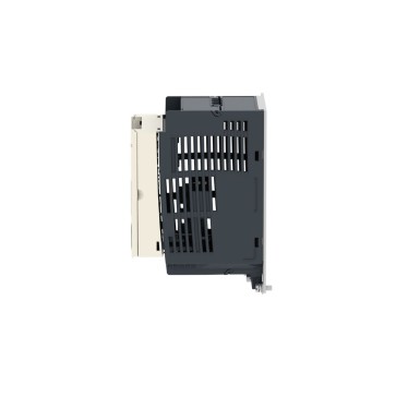
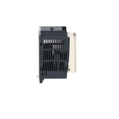
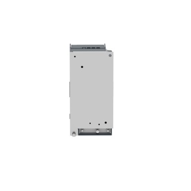


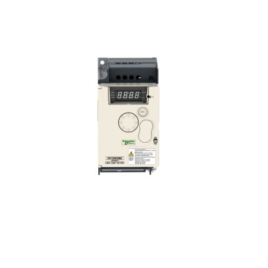


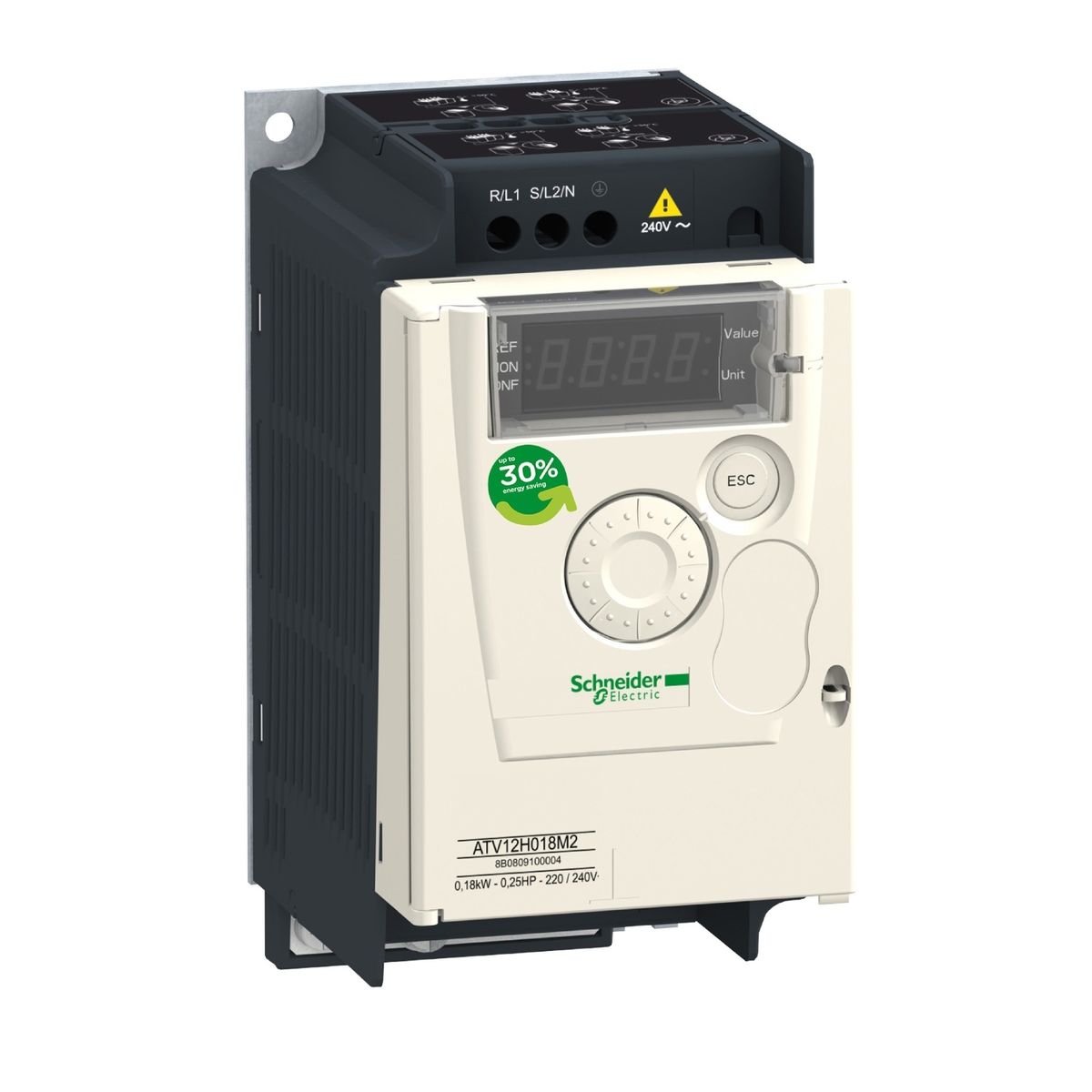


ATV12H037M2 – Schneider Electric
TellitavSingle Register (06) 29 words
Write Multiple Registers (16) 27 words
Read/Write Multiple Registers (23) 4/4 words
Read Device Identification (43)
4...16 kHz with reduction factor
Preset at the factory
4.9 A at 120 V (heavy duty)
4.0 A for 2 s (high overload)
10 ms for analog input
undervoltage
Overcurrent between output phases and ground
Overheating protection
Short circuit between motor phases
Against loss of three-phase input phase
Motor thermal protection via the drive by continuous calculation of I²t
19,2 kbit/s
38,4 kbit/s
Voltage/Frequency Ratio (V/f)
Squared Voltage/Frequency Ratio
S
U
Display unit: 0.1 Hz
<= 1000 m without derating
CSA
C-Tick
UL
GOST
RCM
KC
Electrostatic discharge immunity test level 3 conforming to EN/IEC 61000-4-2
Conducted disturbance immunity level 3 se conforming to EN/IEC 61000-4-6 Radiated
radio-frequency electromagnetic field immunity test level 3 conforming to EN/IEC 61000-4-3
Overvoltage immunity test level 3 conforming to EN/IEC 61000- 4-5
Voltage dips and interruptions immunity test conforming to EN/IEC 61000-4-11
UL 618000-5-1
EN/CEI 61800-5-1
EN/CEI 61800-3
5...95 % without dripping water conforming to IEC 60068-2-3
40…60°C with current reduction of 2.2% per degree
Class 3S2 according to IEC 60721-3-3
emissions with integrated EMC filter environment 1 category C1 conforming to EN/IEC 61800-3 2, 4, 8, 12 and 16 kHz shielded motor cable <5 m
Conducted emissions with integrated EMC filter environment 1 category C2 conforming to EN/IEC 61800-3 2 to 12 kHz shielded motor cable <5 m Conducted
emissions with integrated EMC filter environment 1 category C2 conforming to EN /IEC 61800-3 2, 4 and 16 kHz shielded motor cable <10 m Conducted
emissions with additional EMC filter environment 1 category C1 conforming to EN/IEC 61800-3 4 to 12 kHz shielded motor cable <20 m
Conducted emissions with additional EMC filter environment 1 category C2 conforming to EN/IEC 61800-3 4 to 12 kHz shielded motor cable <50 m Conducted
emissions with additional EMC filter environment 2 category C3 conforming to EN/IEC 61800-3 4 to 12 kHz shielded motor cable <50 m
1.5 mm peak-to-peak (f = 3...13 Hz) - motor not mounted on symmetrical DIN rail - conforming to EN/IEC 60068-2-6
ATV12H037M2 Schneider Electric on lahendus kategooriast Muutuva kiirusega ajamid, mis on mõeldud suurettevõtetele. BaltElec tegeleb mahupõhise müügi ja toodete levitamisega Eestis, Lätis, Leedus ja Soomes.
- Autentne Schneider Electric toode, sertifikaadid ja vastavusdokumendid saadaval.
- Mahupõhine hinnastus – küsi pakkumist suuremate koguste jaoks (võimalik, et sätestame MOQ).
- Tõhus ja kiire logistika Baltikumis ning Soomes; koostöö logistikapartneritega.
- Tehniline tugi ja ettepanekud sobivuse kohta vastavalt Sinu rakendusele.
Hind: Küsi projektipakkumist. Hind sõltub kogusest, tarne- ja maksetingimustest.
KKK tootele ATV12H037M2 - Schneider Electric
-
Kas BaltElec pakub ATV12H037M2 jaoks hulgihinda?
Jah, projektihinnad on saadaval. Saada meile loend soovitud kogustega (näiteks: ATV12H037M2, Schneider Electric, 10tk), et koostaksime projekti pakkumise.
-
Milline on ATV12H037M2 saadavus ja tarne Baltikumis ja Soomes?
Pakume jõudlust Eesti, Läti, Leedu ja Soome suunal. Täpne tarneaeg sõltub konfiguratsioonist ja partii saadavusest; kinnitame pakkumisega.
-
Kas ATV12H037M2 firmalt Schneider Electric on originaaltoode?
Jah. Müüme ainult Schneider Electric originaaltooteid, millel on tootjagarantii. Vajadusel edastame vastavussertifikaadid.
-
Kas ATV12H037M2 sobib minu rakendusse?
Aitame sobivuse kiirelt kinnitada. Edasta palun vajalikud tingimused (pinge, vool, keskkond, standardid) ja võrdleme Schneider Electric tehniliste nõuetega.
-
Kuidas toimub kohaletoimetamine ja arveldamine?
Toimetame kulleriga Eesti, Läti, Leedu ja Soome. Arveldamine vastavalt pakkumisele; projektid ja suuremad kogused hinnastame eraldi.

 Teie avaldus on edukalt saadetud