
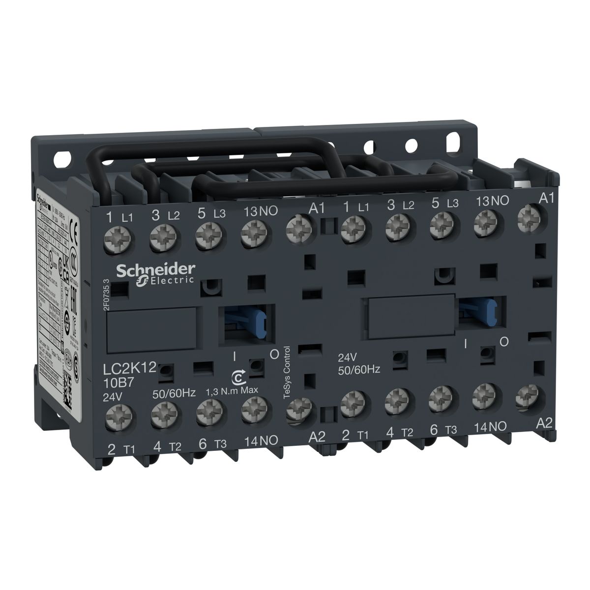
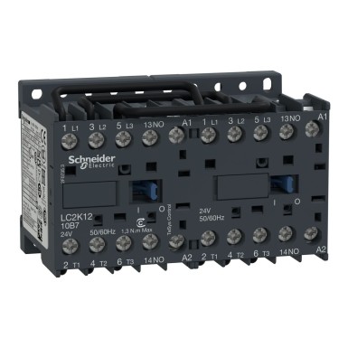
LC2K1210P7 – Schneider Electric
AC-3
AC-4
AC-3e
Motor control (AC-3)
Power circuit: 690 V conforming to IEC 60947-4-1
Signaling circuit: 690 V conforming to IEC 60947-4-1
Signaling circuit: 690 V conforming to IEC 60947-5-1
Signaling circuit: 600 V conforming to UL 508
Power circuit: 600 V conforming to CSA C22.2 No 14
Signaling circuit: 600 V conforming to CSA C22.2 No 14
4 kW at 500 to 600 V AC 50/60 Hz
4 kW at 660...690 V AC 50/60 Hz
3 kW at 220...230 V AC 50/60 Hz
5,5 kW à 380...415 V AC 50/60 Hz
5,5 kW à 440 V AC 50/60 Hz
16 A (at <70 °C) at 690 V AC AC-1 for power circuit
12 A at <= 440 V AC AC-3 for power circuit
12 A at <= 440 V AC AC-3e for power circuit
Signaling circuit: <= 690 V AC 50/60 Hz
80 A at 500 V conforming to IEC 60947
70 A at 660...690 V conforming to IEC 60947
105 A at <50°C - 5 s for power circuit
100 A at <50°C - 10 s for power circuit
75 A at <50°C - 30 s for
55 A power circuit at <50 °C - 1 min for
50 A power circuit at <50 °C - 3 min for
80 A power circuit - 1 s for
90 A signaling circuit - 500 ms for signaling circuit
110 A - 100 ms for signaling circuit
25 A at <50 °C - >= 15 min for power circuit
10 A at <50 °C) for signaling circuit
25 A aM for power circuit
10 A gG for signaling circuit conforming to IEC 60947
10 A gG for signaling circuit conforming to VDE 0660
0.8…1.3 Nm - on flat screw clamp terminals Ø 6 mm
0.8…1.3 Nm - on terminal blocks screw clamp pozidriv n°2
1.3 Mcycles 12 A AC-3 at Ue <= 440 V
1.3 Mcycles 12 A AC-3e at Ue <= 440 V
Screw clamp terminals 1 cable(s) 0.75...4 mm²flexible without cable end Screw clamp terminals
1 cable(s) 0.34... 2.5 mm²flexible with cable end Screw clamp terminals
2 cable(s) 1.5...4 mm²rigid
Screw clamp terminals 2 cable(s) 0.75...4 mm²flexible without cable end Screw clamp terminals
2 cable(s) 0.34...1.5 mm² flexible with cable end
Level loss: 0.2…0.75 Uc (at <50°C)
Contactor closed shocks, on the Y axis: 15 Gn for 11 ms conforming to IEC 60068-2-27
Contactor closed shocks, on the Z axis: 15 Gn for 11 ms conforming to IEC 60068-2-27
Contactor open shocks, on the X axis: 6 Gn for 11 ms conforming to IEC 60068-2-27
Contactor open shocks, on the Y axis: 10 Gn for 11 ms conforming to IEC 60068-2-27
Contactor open shocks, on the Z axis: 10 Gn for 11 ms conforming to IEC 60068-2-27
Contactor closed vibrations: 4 Gn, 5 to 300 Hz conforming to IEC 60068-2-6
Contactor open vibrations: 2 Gn, 5 to 300 Hz conforming to IEC 60068-2-6
Requirement 2 conforming to NF F 16-101
Requirement 2 conforming to NF F 16-102
144 A at 690 V AC for power circuit conforming to IEC 60947
110 A AC for signaling circuit conforming to IEC 60947
Rail
10…20 ms désexcitation bobine + ouverture "F"
B10d = 20000000 contactor cycle with mechanical load conforming to EN/ISO 13849-1
CSA
UKCA
CEI 60947
NF C 63-110
VDE 0660
TC conforming to DIN 50016
Schneider Electric LC2K1210P7 on lahendus kategooriast Tööstuslikud kontaktorid, mis on mõeldud professionaalidele. BaltElec tegeleb mahupõhise müügi ja toodete levitamisega Eestis, Lätis, Leedus ja Soomes.
- Autentne Schneider Electric toode, vastavusdokumendid päringu alusel.
- Mahupõhine hinnastus – küsi pakkumist suuremate koguste jaoks (võimalik, et sätestame MOQ).
- Tõhus ja kiire logistika Baltikumis ning Soomes; koostöö tunnustatud kulleritega.
- Tehniline tugi ja nõustamine valikul vastavalt Sinu rakendusele.
Hind: Küsi projektipakkumist. Hind sõltub kogusest, tarne- ja maksetingimustest.
KKK tootele LC2K1210P7 - Schneider Electric
-
Kas teie pakute LC2K1210P7 jaoks mahupõhist hinda?
Jah, projektihinnad on saadaval. Saada meile loend soovitud kogustega (näiteks: LC2K1210P7, Schneider Electric, 10tk), et koostaksime projekti pakkumise.
-
Milline on LC2K1210P7 saadavus ja tarneaeg Baltikumis ja Soomes?
Pakume jõudlust Eesti, Läti, Leedu ja Soome suunal. Täpne tarneaeg sõltub kogusest ja laoseisust; kinnitame pakkumisega.
-
Kas LC2K1210P7 firmalt Schneider Electric on originaaltoode?
Jah. Müüme ainult Schneider Electric autentseid tooteid, millel on tehase garantii. Vajadusel edastame vastavussertifikaadid.
-
Kas LC2K1210P7 sobib minu projekti?
Aitame sobivuse tõhusalt kinnitada. Edasta palun vajalikud parameetrid (pinge, vool, keskkond, standardid) ja võrdleme Schneider Electric tehniliste nõuetega.
-
Kuidas toimub tarne ja arveldamine?
Toimetame logistikapartneriga Eesti, Läti, Leedu ja Soome. Arveldamine vastavalt kokkuleppele; projektid ja suuremad kogused hinnastame eraldi.
 Teie avaldus on edukalt saadetud