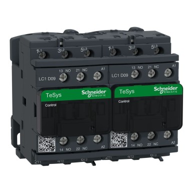
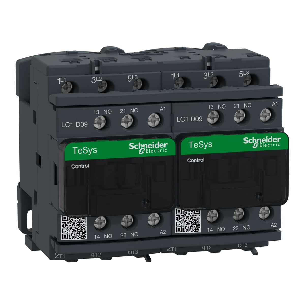
LC2D09E7 – Schneider Electric
TeSys Deca
AC-1
Motor control (AC-3)
TeSys Deca
Power circuit: 600 V CSA certified
Power circuit: 600 V UL certified
Signaling circuit: 690 V conforming to IEC 60947-1
Signaling circuit: 600 V CSA Certified
Signaling Circuit: 600V UL Certified
1 hp at 230/240 VAC 60 Hz for single phase motors
2 hp at 200/208 VAC 60 Hz for 3 phase motors
2 hp at 230/240 VAC 60 Hz for 3-phase motors
5 hp at 460/480 V AC 60 Hz for 3-phase motors
7.5 hp at 575/600 V AC 60 Hz for 3-phase motors
4 kW at 380...400 V AC 50 Hz
4 kW at 415...440 V AC 50 Hz
5,5 kW at 500 V AC 50 Hz
5, 5 kW at 660...690 V AC 50 Hz
25 A (at <60°C) at <= 440 V AC AC-1 for power circuit
Power circuit: <= 300 V DC
61 A power circuit at <40°C - 1 min for
105 A power circuit at <40°C - 10 s for
210 A power circuit at <40°C - 1s for
100 A power circuit - 1s for
120 A signaling circuit - 500 ms for
140 A signaling circuit - 100 ms for signaling circuit
25 A at <60°C) for power circuit
20 A gG at <= 690 V type 2 coordination for power circuit
10 A gG for signaling circuit conforming to IEC 60947-5-1
Power circuit: 1.7 Nm - on screw-clamp terminals - with Phillips No. 2 screwdriver
Remote control: 1.7 Nm - on screw-clamp terminals - with flat screwdriver Ø 6 mm
Remote control: 1.7 Nm - on screw-clamp terminals - with Phillips No. 2 screwdriver
Remote control: 1.7 Nm - on screw-clamp terminals - with n°2 pozidriv screwdriver Power
circuit: 2.5 Nm - on screw clamp terminals - with n°2 pozidriv screwdriver
7 VA 50 Hz cos phi 0.3 (at 20°C)
1 NC mirror contact type conforming to IEC 60947-4-1
2 Mcycles 9 A AC-3 at Ue <= 440 V
Power circuit: screw clamp terminals 2 cable(s) 1...4 mm² flexible without cable end Power circuit: screw clamp
terminals screw clamp 1 cable(s) 1...4 mm²flexible with cable end
Power circuit: screw clamp terminals 2 cable(s) 1...2.5 mm²flexible with cable end
Power circuit: screw clamp terminals 1 cable(s) 1...4 mm²rigid
Power circuit: screw clamp terminals 2 cable(s) 1...4 mm²rigid
Remote control: screw clamp terminals 1 cable(s) 1...4 mm²flexible without cable
end screw clamp 2 cable(s) 1...4 mm²flexible without cable end
Remote control: screw clamp terminals 1 cable(s) 1...4 mm² flexible with cable end
Remote control: screw clamp terminals 2 cable(s) 1...2.5 mm² flexible with cable end
Remote control: screw clamp terminals 1 cable(s) 1...4 mm²rigid
Remote control: screw clamp terminals 2 cable(s) 1...4 mm²rigid
0.8...1.1 Uc -40...60 °C operational AC 50 Hz
0.85...1.1 Uc -40 …60 °C operational AC 60 Hz
1...1.1 Uc 60…70 °C operational AC 50/60 Hz
Contactor closed vibrations: 4 Gn, 5 to 300 Hz
Contactor open shocks: 10 Gn for 11 ms
Contactor closed shocks: 15 Gn for 11 ms
140 A AC for signaling circuit conforming to IEC 60947-5-1
250 A DC for signaling circuit conforming to IEC 60947-5-1
Platine
70 VA 50 Hz cos phi 0.75 (at 20°C)
4…19 ms opening
1,56 W AC-1
B10d = 20000000 contactor cycle with mechanical load conforming to EN/ISO 13849-1
energization between NC and NO contact 1.5 ms on excitation between NC and NO contact
CSA
CCC
UL
GL
LROS (Lloyds register of shipping)
BV
RINA
GOST
UKCA
EN 60947-4-1
EN 60947-5-1
CEI 60947-4-1
CEI 60947-5-1
UL 508
CEI 60335-1
60…70 °C with current reduction
conforming to IEC 60947-1 Annex Q category D
Schneider Electric LC2D09E7 on lahendus kategooriast Tööstuslikud kontaktorid, mis on mõeldud professionaalidele. BaltElec tegeleb mahupõhise müügi ja distributsiooniga Eestis, Lätis, Leedus ja Soomes.
- Originaal Schneider Electric toode, sertifikaadid ja vastavusdokumendid saadaval.
- Mahupõhine hinnastus – küsi pakkumist suuremate koguste jaoks (võimalik, et sätestame MOQ).
- Tõhus ja kiire logistika Baltikumis ning Soomes; koostöö logistikapartneritega.
- Tehniline tugi ja ettepanekud sobivuse kohta vastavalt Sinu rakendusele.
Hind: Küsi projektipakkumist. Hind sõltub kogusest, tarne- ja maksetingimustest.
KKK tootele LC2D09E7 - Schneider Electric
-
Kas BaltElec pakub LC2D09E7 jaoks mahupõhist hinda?
Jah, mahupõhine hinnastus on saadaval. Saada meile loend soovitud kogustega (näiteks: LC2D09E7, Schneider Electric, 10tk), et koostaksime projekti pakkumise.
-
Milline on LC2D09E7 saadavus ja tarneaeg Baltikumis ja Soomes?
Pakume jõudlust Eesti, Läti, Leedu ja Soome suunal. Täpne tarneaeg sõltub konfiguratsioonist ja partii saadavusest; kinnitame pakkumisega.
-
Kas LC2D09E7 firmalt Schneider Electric on originaaltoode?
Jah. Müüme ainult Schneider Electric autentseid tooteid, millel on tootjagarantii. Vajadusel edastame vastavussertifikaadid.
-
Kas LC2D09E7 sobib minu rakendusse?
Aitame sobivuse kiirelt kinnitada. Edasta palun vajalikud parameetrid (pinge, vool, keskkond, standardid) ja võrdleme Schneider Electric tehniliste nõuetega.
-
Kuidas toimub kohaletoimetamine ja arveldamine?
Toimetame kulleriga Eesti, Läti, Leedu ja Soome. Arveldamine vastavalt pakkumisele; suured partiid hinnastame eraldi.

 Teie avaldus on edukalt saadetud